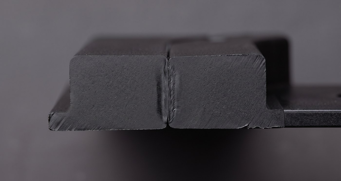
Energy director dimensions, the four joint types and when to use each, near-field against far-field — the decisions that must be made before the mould tool is cut.
Almost every ultrasonic welding problem we are asked about is a joint design problem being attacked with machine settings. Get the joint right and the weld is easy on any decent machine. Get it wrong and no amount of amplitude will rescue it.
A flat face butted against another flat face does not weld well — the energy spreads across the whole area and nothing gets hot enough. An energy director is a small triangular ridge moulded onto one half of the joint. It concentrates all the ultrasonic energy into its apex, which melts first and then flows out to fill the joint.
| Feature | Dimension | Why |
|---|---|---|
| Height | 0.3 to 0.7 mm (0.01–0.04 in) | Enough melt volume to fill the joint without excessive collapse |
| Base width | No more than 20–25% of wall thickness | Wider than that and the energy is no longer concentrated |
| Included angle — amorphous | 90° (ABS, PS, PC, acrylic) | Amorphous resins soften over a range; a broader apex suits them |
| Included angle — semi-crystalline | 60° (nylon, PP, PE, acetal) | Sharp melting point needs a finer point to concentrate energy harder |
| Joint | Best for | Minimum wall | Notes |
|---|---|---|---|
| Butt with energy director | General purpose, easiest to mould | Standard | Simplest and cheapest. No self-location, so tooling has to hold alignment. Flash visible. |
| Step joint | Mechanical strength with better cosmetics | 1.6 mm (0.062 in) | Self-locating, stronger than butt, tolerant of moulding variation. Hides flash on one side. |
| Tongue and groove | Hermetic seals, medical devices | 2.3 mm (0.09 in) | Greatest strength potential. Hides flash inside and out. Hardest to mould — needs tight tolerances. |
| Shear joint | Hermetic seals in semi-crystalline resins | Thinner walls acceptable | Parts telescope together as the edge melts, so the melt never sees air. The answer for nylon and PP. |
Weld depth should be 1.25 to 1.5 times the wall thickness to approach parent-material strength. The interference between the two halves is what does the work — too little and it will not seal, too much and you overload the machine and mark the parts.
This is about where the horn touches the part relative to the joint.
All of the above is cheap to change in CAD and expensive to change in steel. Send the part model and we will have the joint reviewed by application engineers who weld for a living — before the tool exists, not after the first shots fail.
Ultrasonic welding is decided by the parts — the resin, the wall, the joint and what the weld has to do. Send photos and drawings through the enquiry form and you get an engineered answer, not a price range.