Home / Filtration / Hydraulic flushing units
Hydraulic flushing units · Australia

Flush the system until the fluid
proves it clean.

A new or rebuilt hydraulic system fails on the debris left inside it. The HFU 600 flushes the whole system — at up to 600 litres a minute, through staged filtration, with an in-line particle counter deciding when the job is done.

The machine

A flushing plant, not a pump on a trolley

Weld spatter, mill scale, sealant and assembly grit do not leave a hydraulic system on their own — they leave through the first pump, valve or actuator that fails. The only fix is flushing at high velocity, through serious filtration, until the fluid itself proves clean.

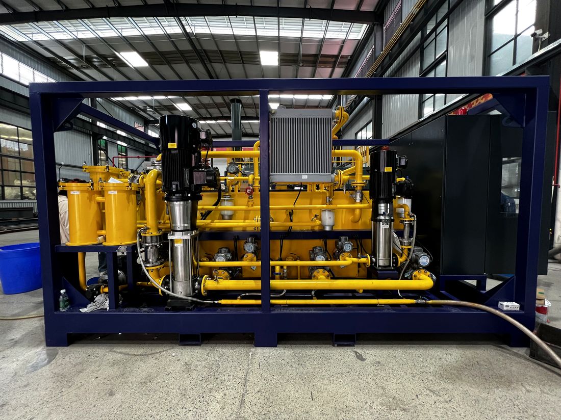
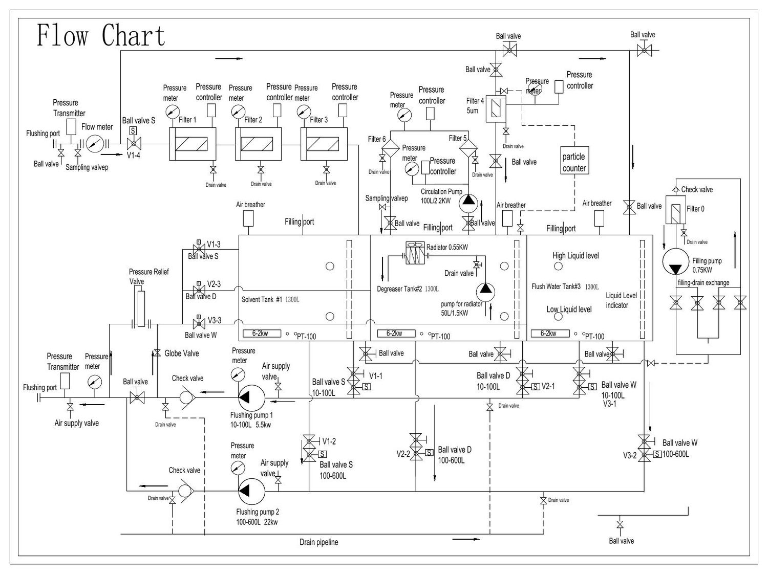
The HFU 600 carries the whole process in one bunded frame: two flushing pumps covering 10 to 600 litres a minute, three heated 1,300-litre tanks — solvent, degreaser and flush water — and up to seven filtration stages down to 5 micron on the return line, with heating, cooling and sampling built in.

Because it degreases, flushes and water-rinses from the same skid, the system is cleaned once, in one connection, to one recorded result.

10–600 L/min · two flushing pumps 3 × 1,300 L heated fluid tanks 7 filter stages · to 5 micron In-line particle counter
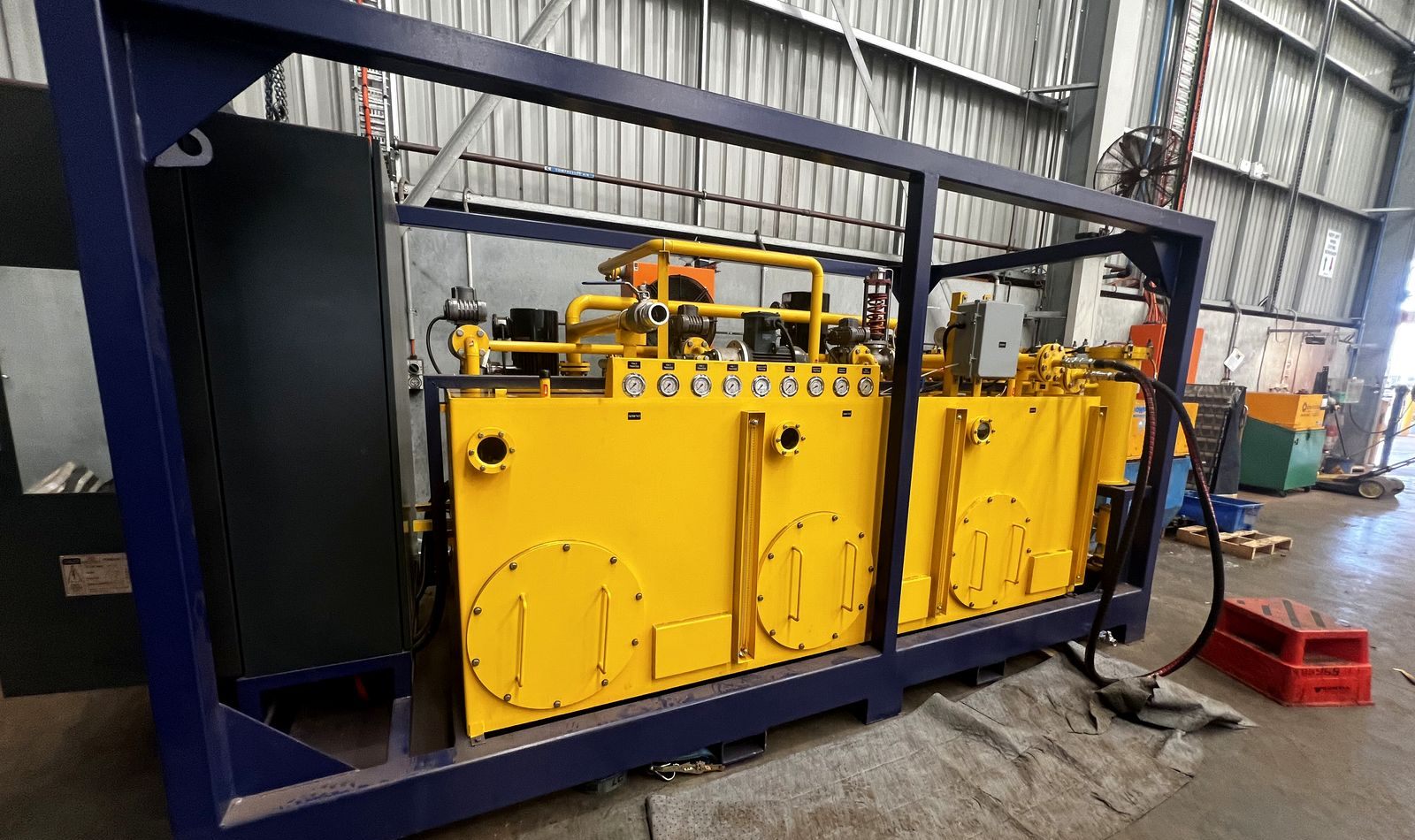
Misonics HFU 600 hydraulic flushing unit — twin fluid tanks and pump set in a bunded transport frame
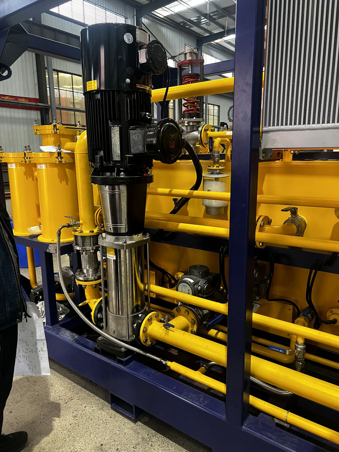
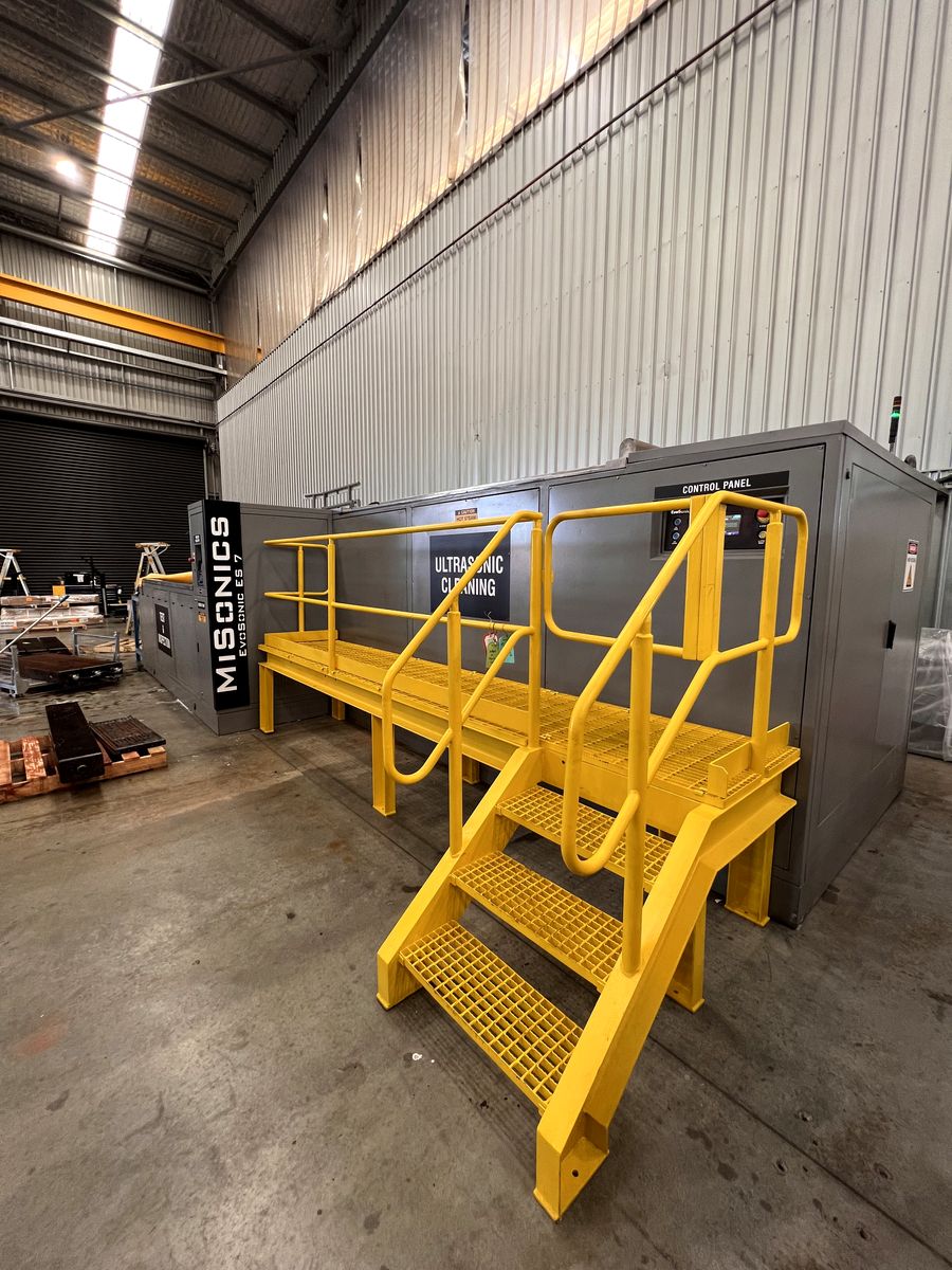
HFU 600 side elevation — filter housings, pump set and fluid tanks HFU 600 pump and pipework detail Misonics machine cabinet with operator access platform
Specification

HFU 600

Flushing flow10 – 600 L/min across two dedicated flushing pumps (5.5 kW and 22 kW)
Process fluidsThree on-board 1,300 L tanks — solvent, degreaser and flush water — so degrease, flush and rinse run from one connection
FiltrationUp to seven staged filters on the circuit, final stage 5 micron
TemperatureHeated tanks with PT-100 control; dedicated radiator circuit for cooling on long flushes
VerificationIn-line particle counter, plus sampling valves for independent laboratory analysis
ProtectionPressure relief, pressure transmitters and flow metering across the circuit
FrameBunded heavy transport frame — craneable, forkable, site-ready

Figures from the HFU 600 build drawings. Larger and smaller duties engineered to order.

How a flush runs

Three steps, one number at the end

1 · Connect

The HFU couples to your system at its flushing ports. Nothing is dismantled beyond the connection points.

2 · Circulate

Hot fluid at high velocity drives contamination out of the pipework and into the staged filters — degrease, flush and rinse from the same skid.

3 · Prove

The in-line particle counter reads the fluid as it circulates. The flush ends when the count reaches your target cleanliness class — and you get the record.

The drawings

Published, like every machine we build

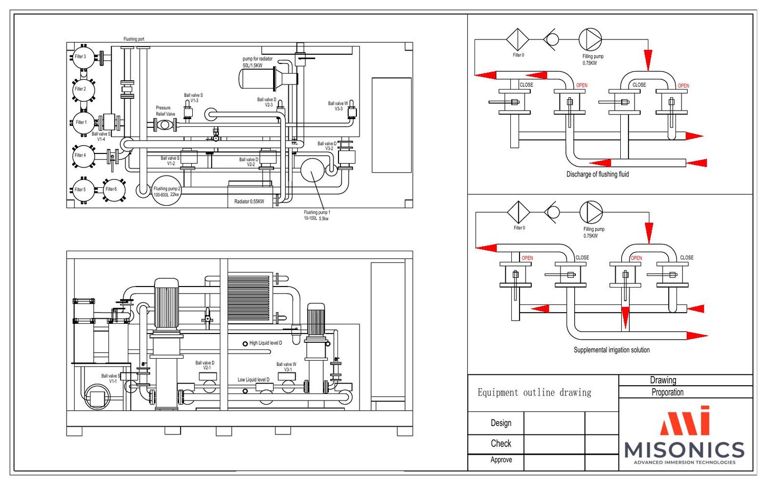
An engineer needs the footprint and the flow path before a machine enters the plant — so here they are. Electrical schematics are supplied with the machine.

HFU 600 equipment outline drawing — Misonics general arrangement HFU 600 flushing circuit flow chart

Tell us about the system

Line sizes, fluid, system volume and the cleanliness class you have to hit. We plan the flush, run it, and hand you the particle counts that prove it.

Book the HFUBack to filtration