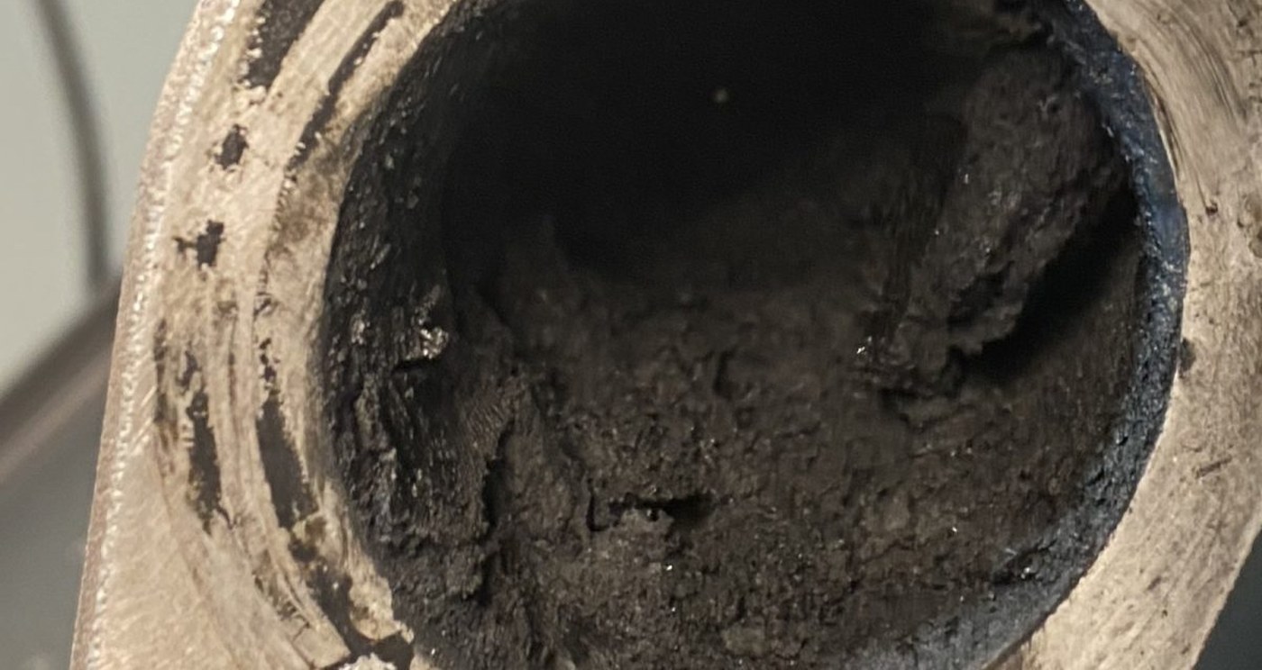
Blind holes, cross-drillings, galleries, internal threads: every machined part hides geometry that no brush enters, no spray turns into, and no inspector can see into either. It is where coolant residues, swarf and cleaning failures all accumulate — and it is the application ultrasonic cleaning was practically invented for. With three caveats that decide whether it actually works.
Cavitation is generated in the liquid itself — wherever solution sits, implosions happen, at full intensity, no line of sight required. A flooded gallery is a cleaned gallery; a filled blind hole scrubs its own floor. The method has no reach limit. It has a liquid-contact limit, and that is the whole game.
A blind hole entering the bath mouth-down keeps its bubble of air, and cavitation cannot happen in a gas. The fixes are orientation and motion: load parts so holes face upward or sideways, and use platform agitation or basket oscillation so trapped air burps out and solution floods in. On automated platforms, programmed vertical agitation does this every cycle without an operator thinking about it.
A 130 kHz bubble field follows a 2 mm drilling much more willingly than a 25 kHz field whose bubbles are large against the bore. For gallery-dense precision work — valve blocks, injector bodies, manifolds — the higher bands earn their place (№4 covers the selection logic). Mixed parts with both heavy externals and fine internals are the dual-frequency case from №10.
Swarf and residue flushed from internals fall into the bath — and an undefended bath puts them back into the next part's galleries. Filtration is non-negotiable for internal-geometry work, and a final rinse (DI where specs demand) clears dissolved residue from passages before it dries there. Verification closes the loop: flow-test or borescope the critical galleries, because "looked clean at the mouth" is not a specification.
Internal cleanliness has exactly one honest language: measurement. Flow-test critical galleries against a known-good baseline; borescope where geometry allows; weigh extraction residue for spec work. "Looked clean at the mouth" has restarted more warranty arguments than any sentence in this industry — the flow sheet ends them.
Gallery-network cleaning with flow verification — manifold work on file.
On file — to be written up: Case Studies/Intake Manifold + Jenbacher Spark PlugsOrient holes up or sideways · agitate to flood · frequency to suit bore size · filter the bath · rinse before drying in the hole · verify by flow or scope, not by eyeball.
Internal cleaning has an evidence problem — the surfaces that matter are the ones nobody can see. Serious programs close it with measurement: flow-testing galleries against specification, borescoping critical bores, or weighing extraction residue per batch. The discipline matters double after any machining rework, where one retained chip in a hydraulic gallery is a warranty claim wearing a delay timer.
Cavitation intensity inside a flooded gallery matches open-tank intensity — the field needs liquid contact, not visibility.Cavitation generation physics — see №1; verified per application by flow testing.
Take the honest worst case: an intake manifold or hydraulic block whose internal network has more surface area inside than out, carrying varnish and particulate from service. The process card that works runs like this. Orientation first: the part goes into the basket with gallery mouths angled upward or sideways so air can leave and liquid can enter — a blind bore facing straight down is a diving bell, and no amount of power cleans a pocket of trapped air. Degas the bath properly before the cycle; gas-saturated liquid quenches cavitation exactly where you need it most, in the confined passages. Then the cycle itself, with agitation or a mid-cycle re-orientation for network geometries — turning the part once halfway through moves the trapped-air problem and the shadowed faces, and costs thirty seconds. Chemistry at the free-rinsing end of the range, because whatever enters those galleries has to leave them: a heavily filmed "protective" chemistry is tomorrow's contaminant in a micro-drilling. Then the flush — rinse water pushed through the network, not just around the part — and drying that actually reaches the internals, because water left in a gallery is flash rust with a schedule.
Verification closes the card: flow-test the critical circuits against a known-good part, and for spec work, extract, filter and weigh. The first time a shop sees what a "cleaned" manifold still sheds into a white bucket of clean solvent, the verification step stops being negotiable.
Valve block, manifold, injector body — the trial returns it flow-tested, with the loading and frequency documented.